- Scale-up without reducing ultrasonic amplitudes.
- Ensure reproducible high-quality results on any scale, from lab to industrial.
- Work with flammable liquids: our transducers are sealed and water-cooled.
- Turnkey: configure a system & get instant pricing.
Scale-Up Must be Done Without Sacrificing Ultrasonic Amplitudes


For most applications of ultrasound, there is a minimum amplitude (typically 70 – 80 microns) below which the application fails due to insufficient processing intensity. With conventional ultrasonic technology, the required amplitudes can only be achieved by laboratory devices and cannot be reproduced on a production scale. Although large conventional ultrasonic processors with high power ratings are available, their maximum amplitudes are very low (only about 20 – 25 microns), which results in severely diminished processing quality.
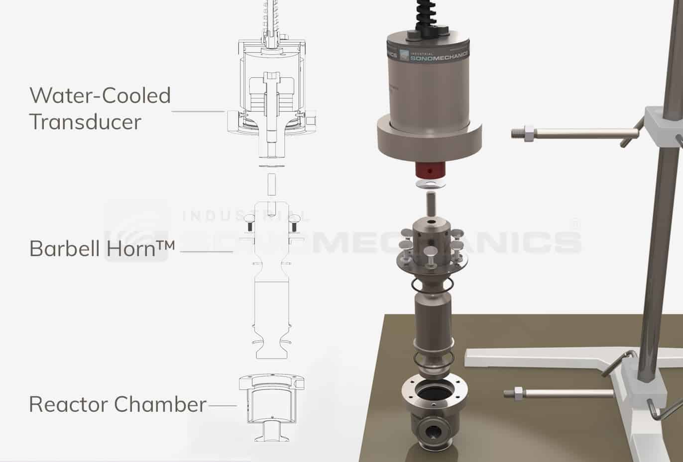
Barbell Horn® Ultrasonic Technology (BHUT)—our core intellectual property—has resolved this issue by making it possible to increase the size of an ultrasonic processor without losing the required high amplitude. BHUT-based laboratory, bench and industrial-scale ultrasonic processors can all provide extremely high ultrasonic amplitudes (over 100 microns). Our customers can, therefore, count on reproducible post-scale-up results, where productivity rates are greatly increased while the highest finished product quality is maintained.
Without Sufficient Amplitudes, Power is Meaningless

For ultrasonic applications, processing intensity is defined by ultrasonic amplitude. By way of analogy, hard-boiling an egg is an application where processing intensity is defined by water temperature, which must reach about 100 oC for this application to be successful. A hard-boiled egg cannot be prepared in a bathtub of warm water—regardless of how much power is spent on warming it—if the required water temperature cannot be reached. Similarly, to produce the desired results, an ultrasonic processor must be able to reach the required amplitude (typically, 70 – 80 microns), regardless of its specified power rating. Once the required amplitude condition is established, however, the power rating does become important, since a larger ultrasonic horn (the vibrating device in an ultrasonic processor) requires more power than a smaller one to be driven at a given amplitude.
Water-Cooling Enables 24/7 Operation & Working with Flammables
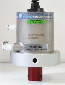
In addition to enabling scale-up without reducing ultrasonic amplitudes, our technology includes another essential (and patented) feature—sealed, water-cooled transducers. A transducer converts the electric energy coming from an ultrasonic generator into mechanical vibrations. High voltages and currents are commonly present in a transducer’s internal area, and substantial heat can be released during its operation. Efficient cooling, especially during continuous processing, as well as protecting the internal area from exposure to humidity or flammable vapors are, therefore, essential conditions.
Conventional transducers are typically cooled by forced air, which makes them prone to overheating during continuous operation (air has low heat removal capacity) and vulnerable to condensation, humidity and flammable vapors, which the air may bring into the internal area where high-voltage contacts are located.
Our water-cooled transducers, on the other hand, can operate continuously (24/7) without overheating and are fully sealed to the outside environment, which makes them immune to high-humidity conditions and suitable for processing flammable materials, such as fuels and organic solvents.